If you own a Bezzera Sole, occasional maintenance and servicing are part of keeping it running at its best. Some components—like the grouphead and steam/hot water wands—are easily accessible from the exterior for routine cleaning and upkeep. Other internal components, such as the boiler and pump, require opening the machine to reach them.
Below are step-by-step instructions to help you safely and easily remove the panels for internal access.
Before you begin: We always recommend powering off your machine and allowing it to cool completely before starting any service. Remove any loose components, including the portafilter, drip tray, and top lid. Unplug the machine and remove the water tank. Accessing certain internal components may require tilting or turning the machine. Taking these steps beforehand helps prevent potential burns, avoids scratches to the machine, and reduces the risk of water spilling from the tank.
To remove the side panels, there is 1 Allen key screw (3/32″) for each side panel that has to be removed/loosened first. The easiest way to tilt the machine forward. To prevent scratching the grouphead, you can place a cloth underneath it, or if you have the original packaging, there is a thick piece of foam you can use.


The top panel is secured by four Allen-head screws (3mm), one located at each corner. Each screw is concealed by a plastic cap; remove these caps using pliers. Remove the four screws and lift off the top panel. Once removed, the boiler, PID controller, pressure gauges, and steam and hot water valve connections are accessible from the top of the machine.


Of the three panels, the rear panel must be removed first. Slide the rear panel upward to disengage it from the chassis. Near the top of the panel is an extended flange that sits beneath tabs attached to the side panels. To release the rear panel, gently flex the side panels outward to clear the tabs, then lift the rear panel away from the machine. Removing the rear panel provides access to the water tank connection, rotary pump, and motor.


Each side panel slides rearward to disengage from the lower panel. The image to the right illustrates a side panel and the corresponding lower-panel hooks. The center feature shown is the screw located underneath the panel, which was removed/unscrewed in an earlier step.


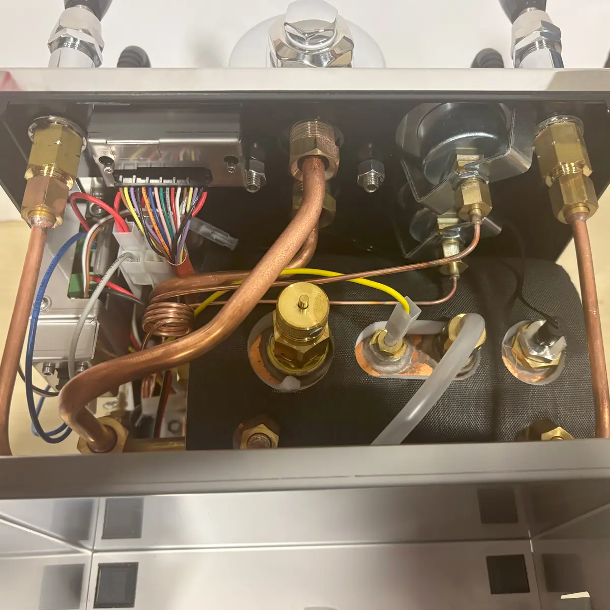
Below are pictures of the inside for your reference.