
Converting 3.5 to 4.0 – VBM Dual Boiler
Disclaimer: The technical statements, support, information and recommendations contained herein are believed to be accurate as of the date hereof, but 1st-line Equipment, LLC does not make representations or warranties, express or implied, as to its accuracy, its completeness, or the results to be obtained. The information is being provided for informational purposes only and is intended for use by persons having adequate skill and expertise regarding the proper selection, use and application of the products and recommendations and at their own risk and discretion.
1st-line Equipment, LLC is not responsible for any injury or damages from such information. Please note that parts are available for purchase from 1st-line Equipment, LLC self service parts portal. These parts do not include any technical support. If you're unfamiliar with the technical aspects of repairing equipment, please contact a professional for proper evaluation.
By continuing to read further, you agree to abide by all the terms and conditions on this website. If you disagree, please leave our website.

- cut tiewrap #1
- unplug #2 and #3
- unscrew #4
- unplug #3b and replace with #2
- unscrew #5


- unscrew #9 and #10 to remove frame #8

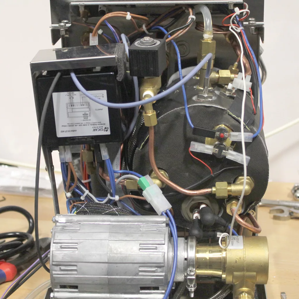
- take note of all wires attached to old brain unit

- take note of all wires attached to old brain unit
- This is part # ELETDOSPIDDS12015

- take note of all wires attached to new brain unit

- take note of all wires attached to new brain unit

new braint unit on top / old brain unit on bottom
- #11 --> #11b
- #12 --> #12b
- #13 --> #13b
- #14 --> #14b
- #7 --> #15

new brain unit on left / old brain unit on right
- #23 --> #23b

- take note of all wires attached to new brain unit

- this is part #
- #25 long end links to #20? gray on the other end
- #26 short end link to #21? blue on the other end

- #20 gray wire links to #25 long on the other end
- #21 blue wire link to #26 short on the other end
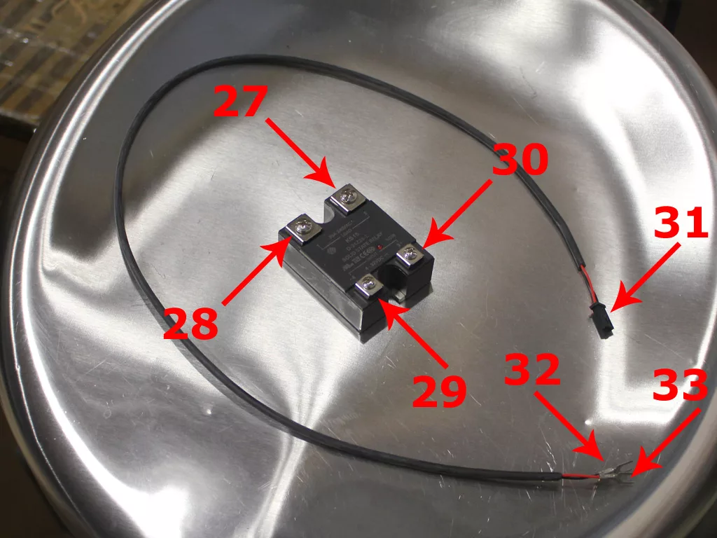

- #32 black wire screws into load 4
- #33 red wire screws into load 3

- #34 is the cover for relay
- #35 is the frame for the brain unit

- #34a and #34b hold the cover for the relay
- #35a and #35b hold the frame for the brain unit
- #36a and #36b hold the relay – note these 2 won’t be easily removed until you remove the cover #34
- now you can move the frame #35 to the side and remove the relay cover #34
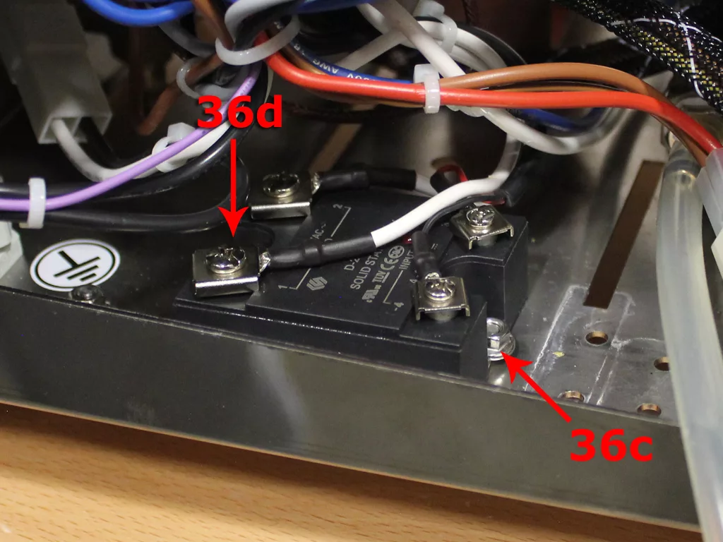
- now you can hold the nuts #36c and #36d to remove the screws

- The new relay will be placed next to the old relay. You will need to drill 2 new holes so both relays can be mounted.
- First put the 2 relays together. Then measure the distance between the openings where the mounting screws go.

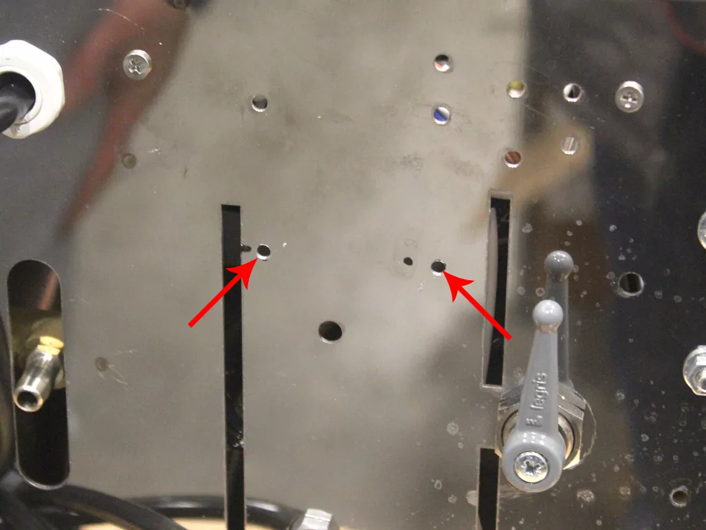
- The new holes you will drill is located in the circles as indicated in the picture to the right
- Measure existing hole for installed relay from a common point, ex right side and top side. Transfer those measurements 1 3/4 inches away from existing holes.
- Drill new holes.
- WARNING: Make sure any parts and wires are cleared on the other side.

- In order for the old relay to fit with the new cover, the wires on load 1 and 2 need to be rotated

- Here is a picture of the new positioning of the wires on load 1 and 2

- Place the old relay inside the machine aligning with the new drilled holes.

- Place the new relay inside the machine next to the old relay.

- Plug #31 into the connection next to #13b

- Place new cover over the relays
- 2 new holes need to be drilled to mount the new cover in place.
- Mark the 2 holes as indictated in the picture.

- Drill new holes.
- WARNING: Make sure any parts and wires are cleared on the other side.

- Insert the new relay cover in and screw in place.
- You can also screw back in the brain unit frame.

- Now we need to modify the power switch.
- Unscrew the switch using an allen key.

- Use a flathead screwdriver to remove the plastic bracket and metal frame

- Slide the see through rubber covering up to get access to the wires

- unscrew the connection with the white wires

- There are 2 white wires: 1 thick, 1 thin. Cut the thin wire.
- The white wire you just cut is tie wrapped to other wires. Slide the white wire out from the rest.

- You can now screw back the connection with the thicker white wire.

- On the heating element of the boiler, you will see a thin white wire similar to the one you cut.

- Remove the wire from the heating element.
- Cut the terminal on the end.

Strip the white covering to reveal the wire underneath.

- Thread the wire from the switch through the heating element cap.

- Twist the 2 wires together.

- Add the terminal to the connected wires.

- Attach the newly constructed wire to the heating element.

- Reinstall the brain unit bracket.
- Contratulations! The machine has now been upgraded. Take note of how the wires are posititoned.
Please note the above information is subject to copyright. It cannot be published by any means without the expressed written consent of 1st-line Equipment, LLC.